Hardware Reference
V7768/V7769*
Intel® Core™ Duo Processor VME Single Board
Computer
THE V7768/V7769 IS DESIGNED TO MEET THE EUROPEAN UNION (EU) RESTRICTIONS OF
HAZARDOUS SUBSTANCE (ROHS) DIRECTIVE (2002/95/EC) CURRENT REVISION.
Organization
This manual is composed of the following chapters and appendices:
Chapter 1 – Installation and Setup describes unpacking, inspection, hardware jumper settings, connector definitions, installation, system setup and operation of the V7768/V7769.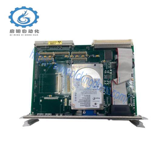
Chapter 2 – Standard Features describes the unit design in terms of the standard PC memory and I/O maps, along with the standard interrupt architecture.
Chapter 3 – Embedded PC/RTOS Features describes the unit features that are beyond standard functions.
Maintenance provides information relative to the care and maintenance of the unit.
Appendix A – Connector Pinouts illustrates and defines the connectors included in the unit’s I/O ports.
Appendix B – AMI BIOS Setup Utility describes the menus and options associated with the American Megatrends, Inc. (system) BIOS.
Appendix C – Remote Booting describes the menus and selections necessary to boot from the SBC remotely
Safety Summary
The following general safety precautions must be observed during all phases of the operation, service and repair of this product. Failure to comply with these precautions or with specific warnings elsewhere in this manual violates safety standards of design, manufacture and intended use of this product.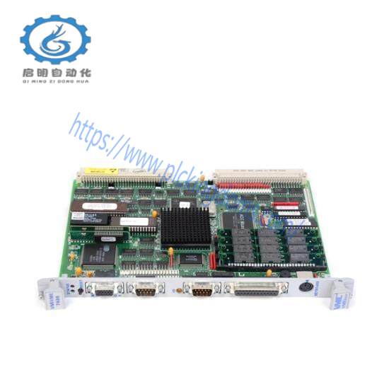
GE assumes no liability for the customer’s failure to comply with these requirements.
Ground the System
To minimize shock hazard, the chassis and system cabinet must be connected to an electrical ground. A three-conductor AC power cable should be used. The power cable must either be plugged into an approved three-contact electrical outlet or used with a three-contact to two-contact adapter with the grounding wire (green) firmly connected to an electrical ground (safety ground) at the power outlet.
Do Not Operate in an Explosive
Atmosphere
Do not operate the system in the presence of flammable gases or fumes. Operation of any electrical system in such an environment constitutes a definite safety
hazard.
Keep Away from
Live Circuits
Operating personnel must not remove product covers. Component replacement and internal adjustments must be made by qualified maintenance personnel. Do not replace components with power cable connected. Under certain conditions, dangerous voltages may exist even with the power cable removed. To avoid injuries, always disconnect power and discharge circuits before touching them.
Do Not Service or
Adjust Alone
Do not attempt internal service or adjustment unless another person capable of rendering first aid and resuscitation is present.
Do Not Substitute
Parts or Modify
System
Because of the danger of introducing additional hazards, do not install substitute parts or perform any unauthorized modification to the product. Return the product to GE for service and repair to ensure that safety features are maintained.
Dangerous
such as the example below, precede only potentially dangerous procedures throughout this manual. Instructions contained in the warnings must be followed.
Installation
The V7768/V7769 conform to the VME physical specification for a 6U board. The V7768/V7769 can be used for the system controller or as a peripheral board. It can be plugged directly into any standard chassis accepting either type of board.
The following steps describe the GE-recommended method for installation and powerup of the V7768/V7769:
If a PMC module is to be used, connect it to the V7768/V7769 prior to board installation (as shown in Figure 1-4 on page 28). Refer to the Product Manual for the PMC module for configuration and setup.
Insert the V7768/V7769 into a VME chassis system controller or peripheral slot. While ensuring that the board is properly aligned and oriented in the supporting board guides, slide the board smoothly forward against the mating connector. Use the ejector handles to firmly seat the board.
3. All needed peripherals can be accessed from the front panel or the rear I/O./
Each connector is clearly labeled, and detailed pinouts are in Appendix A:
Connector Pinouts.
4. Connect a keyboard and mouse if the system has not been previously configured.
5. The V7768 features an optional CompactFlash Disk resident on the board. Refer to Chapter 3: Embedded PC/RTOS Features for setup details.
6. If an external drive module is installed, the BIOS Setup program must be used to configure the drive types. See Appendix B: AMI BIOS Setup Utility to properly configure the system.
7. If a drive module is present, install the operating system according to the manufacturer’s instructions.
BIOS Setup
The V7768/V7769 has an onboard BIOS Setup program that controls many configuration options. These options are saved in a special non-volatile, batterybacked memory chip and are collectively referred to as the board’s CMOS
Configuration. The CMOS configuration controls many details concerning the behavior of the hardware from the moment power is applied.
Details of the V7768/V7769 BIOS setup program are included in
Appendix B: AMI BIOS Setup Utility.
The V7768/V7769 provide front panel access for the PMC expansion site, an optional Gigabit Ethernet port, one 10/100 RJ45 connector, one serial port, SVGA, keyboard/mouse, the manual reset switch and the status LEDs. A drawing of the V7768/V7769 front panels are shown in Figure 1-7 and Figure 1-8. The front panel connectors and indicators are labeled as follows: V7768 • USB Dual USB 2.0 Ports
• LAN1 10/100/1000 Mbit Ethernet connector for port 1
• LAN2 10/100/1000 Mbit Ethernet connector for port 2
• M/K Mouse/keyboard connector
• COM1 Serial Port
• RST Manual reset switch
• BPHT Status LEDs
• VGA Analog Video connector
• A L Activity and Link Status LEDs for rear GbE V7769 • SATA Serial ATA Activity LED
• SAS1 SAS Lane 1
• SAS2 SAS Lane 2
• HB Heartbeat LED for SAS/SATA controller
The V7768/V7769 provide rear I/O support for the following: digital video, two SATA ports, one Serial and four USB ports. The V7768/V7769 are compatible with GE’s Rear Transition Modules ACC-0602RC and ACC-0603RC.
The front panel connectors, including connector pinouts and orientation, for the V7768/V7769 are defined in Appendix A: Connector Pinouts.
The V7768/V7769 are single board computers loaded with either an Intel Core 2 Duo or Celeron M processor and compatible with modern industry standard desktop systems. The V7768/V7769 therefore retain industry standard memory and I/O maps along with a standard interrupt architecture. The integrated peripherals described in this section (such as serial ports, USB ports, CompactFlash drive, video controller and Ethernet controller) are all memory mapped the same as similarly equipped desktop systems, ensuring compatibility with modern operating systems.
Related recommendations:
XYCOM XVME-653
Motorola MVME712M
XYCOM XVME-601
MOTOROLA VME172PA-652SE
Agilent E1406A
XYCOM XVME-976
810-017034-005
SST-PB3-VME-1
XYCOM XVME-564
XYCOM XVME-531
MOTOROLA MVME2304
SST 5136-PBMS-ISA
LAM VME-LTNI-S4 B105-0102
MOTOROLA MVME172LX
KONTRON VMEM-S2
XYCOM XVME-113
SST SST-PB3-VME-2-E
KEBA KVME AT8/486/25B 40240
MOTOROLA MVME133A-20
SST SST-PB3-VME-1-E
SST PB3 Card – SST-PB3-VME-2
5136-CN-VME
GE IS200VTURH1BAC
VME-LTNI-S4 B105-0102
more……
Leave a comment
Your email address will not be published. Required fields are marked *