Call us 24/7+86 18030109652

Mounting IOTA-NR24 units

Up to three (3) IOTA-NR24 units can be fixed on the MCAR-02 with eight ground screws and two power screws (24V and COM) each. 24Vdc power must be connected to the MCAR-02 on the power rails using M5 screws.

Mounting Carrier (36 inch)

The MCAR-03 is a carrier that can be screwed on any flat surface. The MCAR-03 can carry two IOTA-R24 assemblies that can each carry two RUSIO-3224 modules. The “MCAR-03 – top and front view” on the next page shows the physical appearance and the coordinates of the four mounting holes

The MCAR-03 consists of:

A metal profile

Two plastic cover plates

A ground rail with 16 ground connection screws

Two power rails with M5 holes (+24 V and 0 V)

Eight mounting holes (6.35 mm diameter)

Mounting an IOTA-R24

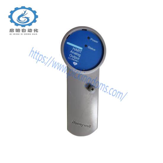
Up to two IOTA-R24 units can be fixed on the MCAR-03 with ten ground screws and two power screws (24 V and COM) each.24 VDC power must be connected to the MCAR-03 on the power rails using M5 screws.Honeywell CC-PAOH01 51405039-175 | High-Precision Analog Input Module for Industrial Automation
Mounting IOTA-NR24 units

Up to three (3) IOTA-NR24 units can be fixed on the MCAR-03 with 22 ground screws and two power screws (24 V and COM) each. Three PDIO01 modules can be fixed to the IOTA-NR24 units.

24 VDC power must be connected to the MCAR-03 on the power rails using M5 screws.

Technical data

General info about chassis

Safety Manager is installed in a cabinet, as described in Cabinet. A cabinet contains the Control Processor modules and the IO modules, which are placed in several chassis:

All Control Processor modules are placed in a Control Processor chassis

All non-redundant IO modules are placed in one or more IOCHAS-0001S or IOCHAS-0002S or IOCHAS-0003S chassis.

All redundant IO modules are placed in one or more IOCHAS-0001R or IOCHAS-0002R or IOCHAS0003R chassis.

A chassis consists of a metal housing, in which the modules, busses and backplanes are placed. The details are described separately for each type of chassis in this chapter.

The housing of a Controller chassis differs from the housing of an IO chassis.

CPCHAS-0001

Chassis for redundant or non-redundant Controller (Safety Manager)

General

The Controller chassis CPCHAS-0001 is used to contain the Control Processor modules. Each Safety Manager has one Controller chassis. The Controller chassis is generally located at the top position in the cabinet, and the IO chassis at lower positions.

A Controller chassis contains the following components:

Controller housing

Controller backplane

Controller housing

The Controller housing has been designed specifically for Safety Manager. It is a 19″ housing that is open at the front and covered at the back.

Control Processor modules are placed in the chassis through the front of the housing with the use of module guides, which are located at the bottom and top plate of the housing.

The modules are locked in the chassis with the quarter turn fasteners, located below the module-grips.

The below figure shows the front of a filled redundant Controller chassis.

The back of the housing is covered by a magnetically locked back cover plate, which can be swung upwards to reveal the Controller backplane.

Cables must be tie-wrapped to one of the three horizontal bars at the back of the housing, to lead them towards the side of the chassis.

The top bar is reserved for the 24V-supply and 24V-signal wires/cables.

The middle bar is reserved for the communication cables.

The bottom bar is reserved for the 5V and Watchdog cables (WdPx and 5V-x).

The below figure shows the back of an empty Controller chassis.

Location of Control Processor modules

The Controller chassis CPCHAS-0001 contains all Control Processor modules.

The below table shows the location of the Control Processor modules in a non-redundant and a redundant Controller (as seen from the front of the cabinet). As you can see, all Control Processor modules are doubled in a redundant Controller configuration, with the exception of the Battery and Key switch module, which is shared by both Control Processors.

CPU1 the processor module of the first Control Processor

QPP-0002 Quad Processor Pack QPP-0002

COM1.1 the first communication module of the first Control Processor

USI-0002 Universal Safety Interface, or FX-USI-0002

BLIND-COM Dummy Communication Module BLIND-COM

COM1.2 the second communication module of the first Control Processor

USI-0002 Universal Safety Interface, or FX-USI-0002

BLIND-COM Dummy Communication Module BLIND-COM

PSU1 the power supply module of the first Control Processor

PSU-240516 Power Supply Unit 24/5 V DC, 16A PSU-240516

BKM the battery and key switch module of (both) Control Processor(s)

BKM-0001 Battery and Key switch Module BKM-0001

CPU2 the processor module of the first Control Processor

QPP-0002 Quad Processor Pack QPP-0002

COM2.1 the first communication module of the second Control Processor

USI-0002 Universal Safety Interface, or FX-USI-0002

BLIND-COM Dummy Communication Module BLIND-COM

COM2.2 the second communication module of the second Control Processor

USI-0002 Universal Safety Interface, or FX-USI-0002

BLIND-COM Dummy Communication Module BLIND-COM

PSU2 the power supply module of the second Control Processor

PSU-240516 Power Supply Unit 24/5 V DC, 16A PSU-240516

In case of a non-redundant Controller, the unused positions in the Controller chassis (CPU2, COM2.1, COM2.2, and PSU2 are covered by an BLIND-CPS plate (see Figure 6-2). For each Quad Processor Pack, room is provided for two communication modules in the Controller chassis. The below table shows possible locations for different combinations of communication modules.
Related product recommendations:
GE NP104X905BA482
Allen-Bradley Kinetix  2198-DB335
YOKOGAWA AIP830-101
A16B-1310-0380
HIMA HIMATRIX F1DI16 01
ABB 5SDA1444F0005
ABB 3BHE024328R0101
FOXBORO P0911LD
Allen-Bradley 2094-EN02D-M01-S1
A-B 800H-JR2KB7XAXX30mm
Allen Bradley 1414-CTQ03PDDAA
GE IS200VSV0H1B
GE R2X0N1A0B1T0ARXi2
CAREL PCO3000EL0
Allen Bradley 141A-VS135MCS
Emerson HD22010-2}
More…

Product Specifications

Interconnect Assemblies

Trident baseplates within a single I/O column are connected by Interconnect Assemblies that carry I/O messages and logic power across the baseplates. The MP Interconnect is connected to an I/O baseplate, and the I/O Interconnects are connected to other I/O Baseplates.

MP Interconnect Assembly

Physically, an MP Interconnect Assembly consists of a small passive PCB in a molded plastic housing with two DIN-C 96-pin male connectors. The assembly is attached to the top or bottom of an MP Baseplate in order to connect adjacent I/O Baseplates. The MP Interconnect Assembly also is used on AI and AO HART Baseplates because they are the same size as MP Baseplates.

I/O Interconnect Assembly

Physically, an I/O Interconnect Assembly consists of a small passive PCB in a molded plastic housing with two DIN-C 96-pin male connectors. The assembly is attached to the top or bottom of an I/O baseplate in order to connect other I/O Baseplates.

Required Accessories

The following accessories are required to protect Trident components from dust, liquids and corrosive atmospheres:

• End caps

• Terminal covers

• Slot covers

End caps protect the top and bottom of each end-of-column baseplate and serve as a card guide. They are available for both MP Baseplates and I/O Baseplates.

Terminal covers protect any terminals on a baseplate that are not connected to field wiring.

Slot covers protect unused baseplate slots.
Related product recommendations:
Allen Bradley IR46829982M90-110/132
Rockwell Automation 2071-AP4
K&S AS-261-0-02
Bently Nevada 3300/30
GE IC756WDJ009K-23
Emerson 8034-CC-128000IS
Allen Bradley 837-A9AX706
Yokogawa ATI3S-00 S2
ControlTech EE-4596-211-009
SIEMENS SIMATIC HMI TP900
ABB INNPM22
AB 1792D-4BV0D
A-B 800TC-H3216A30mm
Tellabs 9195 Network Telecom
WOODWARD 5461-117
Yokogawa TYPE-DU-2
More…….

Procedure to Set the Date and Time-T9110

1. Unlock the RTC Read variable so it turns FALSE.

2. Select each RTC Program Rack variable and enter the date and time values.

3. Toggle the RTC Write variable TRUE then FALSE to write the new date and time setting to the processor.

4. Lock and force the RTC Read variable to TRUE.

5. The RTC Status rack now displays the new date and time of the processor.

6. Unlock all the RTC Control variables.

Install I/O ModulesICS TRIPLEX T9110 Industrial Control Module

Do the following:

• Before inserting a new I/O module, examine it for damage.

• The identification labels on the sides of the I/O module will be hidden when the module is installed. Therefore before installation write down the location of the module and the details shown on the label.

Installation

1. Examine the coding pegs on the termination assembly and make sure that they complement the sockets on the rear of the new I/O module.

2. Place the I/O module on to the dowel pins on the T9300 I/O base unit. Make sure the slot on the head of the module clamp screw is vertical and then push the module home until the module connectors are fully mated with the I/O base unit and termination assembly connectors.

3. The locking screw requires a quarter turn clockwise to lock. Use a broad (9mm) flat blade screwdriver to lock the clamp screw. The locking screw acts as a power interlock device and must be in the locked position when poweris applied otherwise the module will not be configured.

Install T9310 Expansion Cables

Use T9310 expansion cables to connect additional groups of T9300 I/O base units.

The ferrites supplied with the expansion cable are snap on components. Fit the ferrites 50 mm (2 in.) from each end and secure with cable ties either side of the ferrites.

Connect Expansion Cable between T9100 Base Unit and T9300 I/O Base unit (I/O Bus2)

1. Connect the expansion cable to a T9100 processor base unit for an I/O Bus 2 connection.

• Insert a cable socket assembly into the left hand connector of the T9100 processor base unit.

• Secure the socket assembly by inserting the two M3 socket cap screws.

• Tighten the screws with a 2.5 mm Allen key.

• Install the cable to the socket assembly and tighten the retaining screws by hand.

2. Insert the free end of the expansion cable into a right hand socket of a T9300 I/O base unit.

• Insert a cable plug assembly into the right hand socket of the processor or I/O base unit.

• Secure the plug assembly by inserting the two M3 socket cap screws.

• Tighten the screws with a 2.5 mm Allen key.

• Install the cable to the plug assembly and tighten the retaining screws by hand.

1. Connect the expansion cable between a T9100 processor base unit (or a T9300 I/O Base unit) to a T9300 I/O base unit.

• Insert a cable plug assembly into the right hand socket of the processor or I/O base unit.

• Secure the plug assembly by inserting the two M3 socket cap screws.

• Tighten the screws with a 2.5 mm Allen key.

• Install the cable to the plug assembly and tighten the retaining screws by hand.

2. Connect the free end of the expansion cable to the left hand plug of an I/ O base unit using a cable socket assembly.

• Insert a cable socket assembly into the left hand connector of the T9300 processor base unit.

• Secure the socket assembly by inserting the two M3 socket cap screws.

• Tighten the screws with a 2.5 mm Allen key.

• Install the cable to the socket assembly and tighten the retaining screws by hand.

Fault Reporting Reference Information

Each module has a set of front panel status indicators. The function and meaning of these indicators related to each module is as follows:

Status Indicators on the T94xx Series Input and Output Module

Power Distribution and First Power Up

The power distribution and first power up verifies that the power distribution circuits function as designed and as detailed in the drawings. It shows the correct voltages are appearing, and only in the correct places. It also provides an opportunity to verify correct operation of any power indicators outside the controller itself.

Do the following:

1. Make sure all modules are removed.

2. Trip all circuit breakers and disengage all power distribution fuses and field fuses.

3. Apply power to the incoming power terminals.

4. It is good practice to switch on power supplies to field devices before supplies to the controller. Devise a formal sequence in which to switch on individual circuits.

• In sequence, check each circuit breaker orfuse for zero volts on the destination side, and then close the circuit breaker or fuse and verify that the appropriate voltage appears.

• Check that any associated power indicator is lit.

• As each circuit breaker is tested, leave the breaker in the ‘on’ position so that any unwanted connection between different power circuits can be detected.

5. Trip and re-instate each circuit breakerin turn and verify the correct circuits are isolated and restored. Similarly disengage and replace each fuse and verify the associated circuits.

6. At the same time verify correct operation of any power indicators supplied with the system.
Related product recommendations:
ABB 3HAA001-CE
GE DS3800NTCF1C1C
Bently Nevada 330104-00-18-10-02-CN
Allen Bradley 705330-93S
ENTEK E2170/1/80 CORD
RELIANCE 0-51851-6
KEMO 618P-RDB7C
ABB 216NG62A HESG441634R1/K HESG216876
Emerson Ovation 1C31166G01 & 1C31169G02
Yokogawa ADV151-P50-S2
REXROTH MDD071C-N-040-N2T-095GB0
Rockwell Automation 800H-Y51J800H PB
SIEMENS 6ES5941-7UA12 CPU941
A-B 188-K2D500
A-B 800H-JR2KU7DDKK30mm
TRICONEX TRICON 3805H
GE IC756LDV000J-99
ABB NGPS-11
ABB 3HNE 01841-1 Door
Rockwell Automation 1747-PTA1E
More…

3500-40M Proximitor Monitor Datasheet – 141535

Description

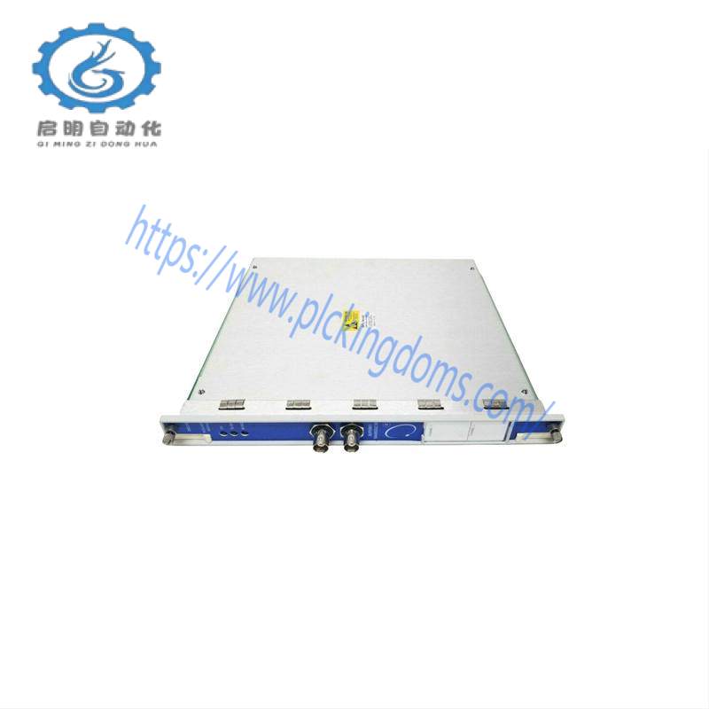
The3500/40M Proximitor Monitoris a four-channel monitor that accepts input from Bently Nevada proximity transducers, conditions the signal to provide various vibration and position measurements, and compares the conditioned signals with user-programmable alarms. The user can program each channel of the 3500/40M with the 3500 Rack Configuration Software to perform any of the following functions:

Radial vibration

Eccentricity

REBAM

Thrust position

Differential expansion

The primary purpose of the3500/40MProximitor Monitoris to provide the following:BENTLY 1900/65A-00-01-01-01-01 Industrial Module

Machinery protection by continuously comparing monitored parameters against configured alarm setpoints to drive alarms

Essential machine information for both operations and maintenance personnel

Each channel, depending on configuration, typically conditions its input signal to generate various parameters called static values. You can configure alert setpoints for each active static value and danger setpoints for any two of the active static values.

Alarm Setpoints

Use Rack Configuration Software to set alert levels for each value measured by the monitor and Danger setpoints for any two of the values measured by the monitor.

Alarms are adjustable from 0 to 100% of full-scale for each measured value. However, when the full-scale range exceeds the range of the transducer, the range of the transducer will limit the setpoint.

Compliance and Certifications FCC

This device complies with part 15 of the FCC Rules. Operation is subject to the following two conditions:

This device may not cause harmful interference.

This device must accept any interference received, including interference that may cause undesired operation.

EMC

European Community Directive: EMC Directive 2014/30/EU

Standards:

EN 61000-6-2 Immunity for Industrial Environments

EN 61000-6-4 Emissions for Industrial Environments

Electrical Safety

European Community Directive: LV Directive 2014/35/EU

Standards: EN 61010-1

RoHS

European Community Directive: RoHS Directive 2011/65/EU

Maritime

ABS-Marine and Offshore Applications DNV GL Rules for Classification – Ships, Offshore Units, and High Speed and Light Craft

Ordering Considerations

General

The 3500/40M Module requires the following (or later) firmware, and software revisions:

3500/01 Software – Version 2.50

3500/02 Software – Version 2.20

3500/03 Software – Version 1.21

When ordering I/O Modules with External Terminations the External Termination Blocks and Cable must be ordered separately for each I/O Module.

External Termination Blocks cannot be used with Internal Termination I/O Modules.

Internal Barrier I/O Modules

Consult the 3500 Internal Barrier specification sheet (document 141495) if the Internal Barrier Option is selected.

REBAM

The REBAM channel type requires the following (or later) firmware, and software revisions:

3500/40M Module Firmware – Revision 2.1

3500/01 Software – Version 3.30

3500/02 Software – Version 2.40

3500/03 Software – Version 1.40

DM2000 Software-Version 3.40.

Requires the M version of the 3500 Proximitor Monitor.
Related product recommendations:
Bently Nevada 3500/40 176449-01
Bentley Nevada 200152-15-00
Bently Nevada 330103-00-20-10-02-00
Bently Nevada 330103-A00-B10-C10-DO2-E00
Bently Nevada 135613-02
Bently Nevada 330903-00-09-10-02-CN
Bently Nevada 3500/72M
Bently Nevada 330103-09-15-05-02-00
Bently Nevada 330103-00-06-50-02-00
Bently Nevada 81725-02
Bently Nevada 330103-00-05-10-02-00
Bently Nevada 3500/15
Bently Nevada 3500/40 
Bently Nevada 990-05-XX-01-00 165335-01
Bently Nevada 1900/65A-01-02-01-00-00
Bently Nevada 330173-00-18-10-02-05
More…

Specifications and Ordering Information 3500/53 Electronic Overspeed Detection System

Description

Bently Nevada’s Electronic Overspeed Detection System for the 3500 Series Machinery Detection System provides a highly reliable, fast response, redundant tachometer system intended specifically for use as part of an overspeed protection system. It is designed to meet the requirements of American Petroleum Institute Standards 670 and 612 pertaining to overspeed protection.

3500/53 modules can be combined to form a 2-out-of-2 or 2-out-of-3 (recommended) voting system.

The use of redundant power supplies in a 3500 rack containing the Overspeed Detection System is required.

Inputs

Signal:Each Overspeed Detection module accepts a single transducer signal from a proximity probe transducer or magnetic pickup. The input signal range is +10.0 V to -24.0 V. Signals exceeding this range are limited internally by the module.BENTLY 3500/92 136180-01 Control Module

Transducers:Bently Nevada 3300 8 mm Proximitor®; 3300 16 mm HTPS, 7200 5 mm, 8 mm, 11 mm, and 14 mm Proximitor®; 3300 RAM Proximitor®, or Magnetic pickups.

Alarm LEDs: Indicates that an alarm condition has occurred with the associated relay

Buffered Transducer Outputs: The front of each module has one coaxial connector for buffered output. Each connector is short circuit and ESD protected.

Recorder: +4 to +20 mA. Values are proportional to module full-scale range (rpm). Module operation is unaffected by short circuits on recorder output

Resolution: 0.3662 µA per bit ±0.25% error at room temperature ±0.7% error over temperature range. Update rate approximately 100 ms.

Speed Input: The 3500 Overspeed Protection Module will support from 1 to 255 events per revolution with a maximum full-scale range of 99,999 rpm and a maximum input frequency of 20 kHz. Minimum input frequency for proximity transducers is 0.0167 Hz (1 rpm for 1 event/revolution) and for passive magnetic pickups is 3.3 Hz.

RPM Accuracy: Less than 100 rpm = ± 0.1 rpm, 100 to 10,000 rpm = ±1 rpm, 10,000 to 99,999 rpm = ± 0.01%.

Auto Threshold: Use for any input above 0.0167 Hz (1 rpm for 1 event/revolution). Minimum signal amplitude for triggering is 1 volt peak-to-peak.

Manual Threshold: User selectable from +9.9 Vdc to -23.9 Vdc. Minimum signal amplitude for triggering is 500 millivolts peak-to-peak.

Alarm Setpoints: Under and Over Alert levels (setpoints) can be set for speed. In addition, a Danger (Overspeed) setpoint can be set for speed. All alarm setpoints are set using software configuration. Alarms are adjustable and can normally be set from 0 to 100% of full-scale of speed full-scale range.

General

If the 3500/53 is added to an existing 3500 System the following firmware and software versions (or later) are required:

3500/20 Module Firmware – Revision G

3500/01 Software – Version 2.00

3500/02 Software – Version 2.03

3500/03 Software – Version 1.13

The use of redundant power supplies in a 3500 rack containing the Overspeed Detection System is required.

133388-01 3500/53 Overspeed Detection Module

133396-01 Overspeed Detection I/O Module

04425545 Grounding Wrist Strap (single use)

04400037 IC Removal Tool

134129-01 Firmware IC

00580438 Connector Header, Internal Termination, 4-position, Green

00580436 Connector Header, Internal Termination, 6-position, Green

00580432 Connector Header, Internal Termination, 10-position, Green

134939-01 3500/53 Overspeed Detection Manua
Related product recommendations:
Bently Nevada 3500/20 125744-04
BENTLY 3500/20 125760-01
Bently Nevada 3500/20-01-01-00
Bently Nevada 3500/20 125744-02
Bently Nevada 3500/20
BENTLY 3500/20
Bently Nevada 3500/20 125744-01
Bently Nevada 3500/20-02-01-00
BENTLY 3500/20 125744-01
BENTLY 3500/20 125744-02
BENTLY 3500/20 125768-01
BENTLY 3500/20 125744-02
Bently Nevada 3500/20 125744-02
Bently Nevada 3500/20-01-02-CN
Bently Nevada 3500/20
Bently Nevada 3500/20-01-01-00
Bently Nevada 3500/20-01-02-00
Bently Nevada 3500/20
Bently 3500/94
102618-01
Bently Nevada 125744-02
More…

3500-15 AC and DC Power Supplies Datasheet – 141530

Description

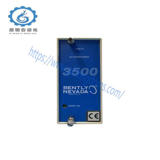
The 3500/15 AC and DC Power Supplies are half-height modules and must be installed in designated slots on the left side of the rack. The 3500 rack can contain one or two power supplies with any combinations of AC and DC. Either supply can power a full rack.

When two power supplies are installed in a rack, the one in the lower slot acts as the primary supply, and the other in the upper slot acts as the backup supply. If installed, the second supply is the backup for the primary one.

Removing or inserting either power supply module does not disrupt operation of the rack as long as a second power supply is installed.Bently 3300/16-03-01-01-00-00-01 - Reliable Industrial Monitoring Module

The 3500/15 AC and DC Power Supplies accepts a wide range of input voltages and converts them to voltages acceptable for use by other 3500 modules. The following power supplies are available with the 3500 Series Machinery Protection System:

Universal AC Power

High Voltage DC Power Supply

Low Voltage DC Power Supply

Compliance and Certifications FCC

This device complies with part 15 of the FCC Rules. Operation is subject to the following two conditions:

This device may not cause harmful interference.

This device must accept any interference received, including interference that may cause undesired operation.

EMC

European Community Directive: EMC Directive 2014/30/EU

Standards:

EN 61000-6-2; Immunity for Industrial Environments

EN 61000-6-4; Emissions for Industrial Environments

Electrical Safety

European Community Directive: LV Directive 2014/35/EU

Standards: EN 61010-1

RoHS

European Community Directive: RoHS Directive 2011/65/EU

Maritime

DNV GL rules for classification – Ships, offshore units, and high speed and light craft

ABS Rules for Condition of Classification, Part 1

Steel Vessels Rules

Offshore Units and Structures

cNRTLus

Class I, Zone 2: AEx/Ex nA nC ic IIC T4 Gc;

Class I, Zone 2: AEx/Ex ec nC ic IIC T4 Gc;

Class I, Division 2, Groups A, B, C, and D;

T4 @ Ta= -20˚C to +65˚C (-4˚F to +149˚F) When installed per drawing 149243 or 149244.

ATEX/IECEx

Ex nA nC ic IIC T4 Gc

Ex ec nC ic IIC T4 Gc

T4 @ Ta= -20˚C to +65˚C (-4˚F to +149˚F)

When installed per drawing 149243 or 149244.

1. 3500/15 AC and DC Power Supplies OK LED

2. Legacy Low Voltage DC Power Input Module

3. Legacy High Voltage DC Power Input Module

4. Legacy High Voltage AC Power Input Module

5. Legacy Low Voltage AC Power Input Module

6. Universal AC Voltage Power Input Module

7. High Voltage DC Power Input Module

8. Low Voltage DC Power Input Module
Related product recommendations:
Bently Nevada 3500/40M-03-00
Bently Nevada 5300 08-050-03-00
BENTLY 1900/65A-00-01-01-01-01
Bently Nevada 330173-04-08-10-02-00
Bently Nevada 22811-00-03-10-02
BENTLY 3500/92 136180-01
BENTLY NEVADA 330101-33-66-10-02-05
BENTLY 33088 53-01-03
Bently Nevada 330704-00-080-10-01-05
BENTLY 190171-0875
Bently Nevada 330930-045-01-05
Bently Nevada 900800XL
BENTLY NEVADA 3389-02
BENTLY NEVADA  330103-00-07-05-02-CN
BENTLY NEVADA 146031-01 18E024JJ
Bently Nevada 330104-05-13-10-02-00
BENTLY 3500/70M 176449-09
BENTLY NEVADA 330104-00-06-05-01-05
Bently Nevada 330103-000-080-10-02-00
BENTLY 1900-65A-01-00-01-00-00
More…

GM unveils new high-performance Cadillac Lyriq, plans to lead luxury electric vehicle sales by 2025

DETROIT — General Motors on Thursday unveiled an $80,000 all-electric Cadillac Lyriq performance version as the Detroit automaker aims to become the best-selling luxury electric vehicle brand in the U.S. this year.

Cadillac hopes to achieve that goal with an expanding lineup of electric vehicles, such as the high-performance Lyriq-V, Escalade IQ SUV and the upcoming entry-level Optiq crossover.

“We will position Cadillac as the best-selling luxury electric vehicle brand in the U.S. in 2025. Let me repeat that: the best-selling luxury electric vehicle [brand] in 2025,” Cadillac Vice President John Ross said at a news conference. “There’s no limit to what we can do in the luxury electric vehicle space.”

But the “luxury” space may not be as clear-cut as it seems. Cadillac said after Ross’ comments that it won’t include Tesla in its lineup Cadillac is positioning itself as a “luxury” automaker, even though some of its products are priced in the same ballpark as some of its rivals. A brand spokesman said Cadillac lists brands such as Audi and Mercedes-Benz as its core competitors.

“There are a few models in the Tesla lineup that may fit the luxury positioning, but they still incorporate some interesting elements into the brand,” Ross said.

In addition to Tesla, which is far ahead in the US electric vehicle market, Cox Automotive reported that Cadillac sold nearly 30,000 electric vehicles last year, just behind BMW’s approximately 51,000. Audi and Mercedes-Benz also have sales close to Cadillac. In contrast, Cox estimates that Tesla sold more than 633,000 electric vehicles in the United States last year.

Historically, the auto industry has been made up of “mainstream” brands such as Chevrolet and luxury brands such as Cadillac. But today, many brands, including Cadillac and Tesla, offer vehicles across a wide range of prices.

Tesla’s pricing ranges from about $42,500 for the Model 3 sedan to about $100,000 for vehicles like the Cybertruck and Model S Plaid. By comparison, Cadillac’s electric vehicles, once available, are expected to range in price from $54,000 for the Optiq to more than $150,000 for the Escalade IQ. Cadillac also offers a custom car, the Celestiq, for more than $300,000.

For reference, Kelley Blue Book reports that the average transaction price for a new electric vehicle was $55,544 at the end of last year. That doesn’t include consumer EV incentives, such as a federal tax credit of up to $7,500.

Cadillac expects to have five electric vehicles on the market by the end of the year, compared to three currently. That would put it on par with Tesla’s number of electric vehicles, but Tesla’s share of the U.S. electric vehicle market was still estimated to be close to 50% last year

As for the Lyriq-V, Cadillac says it will have about 615 horsepower, 650 foot-pounds of torque and a 285-mile range on a full charge. 0-60 mph acceleration is expected to be as fast as 3.3 seconds.

The Lyriq is Cadillac’s first mass-produced electric vehicle and is included in its high-performance V-Series model. The Lyrq-V is generally similar to the regular model but includes unique badging and enhanced performance parts and other accessories to improve driving dynamics.

GM says the Lyriq-V will start at $79,995 and will be sold in the U.S., Canada and other countries, with production to begin in early 2025 at GM’s Spring Hill manufacturing plant in Tennessee.
Related product recommendations:
AMAT 0100-14003
REXROTH DKS11-W100A-DA01-01
Siemens Simodrive 6SN1118-0NK01-0AA2
ABB 216NG63
Westinghouse Ovation 5X00241G01
ABB 3BHE036342R0101
A-B 598-DC563014T NEMA 4/4X
Emerson 336A5026ENG006MM
ABB DSAI130 57120001-P
Allen-Bradley 1756-DNB
GE CL02D400TD
Allen-Bradley 2711P-T6C21D8S
Rockwell A-B 64418-VARELAY
Rockwell A-B 800T-7PY800T 30
Bently Nevada 133388-02
Bosch Rexroth R911286193 MHD112D-027-NP3-BN
More……

Bodies of all 67 victims of Washington plane crash found, officials say

The bodies of 67 people killed in Wednesday’s crash of an American Airlines jetliner have been recovered from two regional jets and an Army Black Hawk helicopter over the Potomac River, officials said Tuesday. The Washington Fire and EMS Department said 66 of them have been identified.

The National Transportation Safety Board, which is leading the investigation, said Tuesday that a display screen at the air traffic control tower showed the helicopter was about 300 feet at the time of the collision. That’s 200 feet higher than the maximum altitude helicopters can fly in the area, according to Federal Aviation Administration regulations, but the NTSB warned that more information is needed, which will be provided after the Black Hawk is pulled from the water.

Rescuers have been working over the past few days to remove the wreckage of the Bombardier CRJ-700 aircraft. So far, rescuers have taken out the right wing, the center fuselage, a section of the front of the cabin, the tail cone and other parts.

American Airlines Flight 5342, operated by its regional subsidiary PSA Aviation, collided with a helicopter seconds before landing at Reagan National Airport in Washington, D.C., killing all 64 passengers and three military crew members aboard the Black Hawk. Officials said the helicopter was on a training mission.

It was the worst U.S. air disaster since 2001 and the first fatal large passenger plane crash in the country in nearly 16 years.

Investigators are still looking into the cause of the collision. The NTSB said it had questioned air traffic controllers on duty that night, including those who were working at the time of the collision.

The NTSB has recovered two data recorders from the American plane, as well as the recorder from the Black Hawk helicopter.

“NTSB investigators continue to transcribe the cockpit voice recorders from both aircraft. Synchronization of the Black Hawk flight data recorder and cockpit voice recorder is ongoing,” the NTSB said Tuesday.

The Federal Aviation Administration on Friday announced an indefinite ban on helicopter flights in the area near the airport.

American Airlines CEO Robert Isom told employees in a note Tuesday that the company will observe a minute’s silence on Wednesday to mark the one-week anniversary of the crash.

“Caring for and supporting all those affected by this tragedy remains our top priority,” Isom said as he visited Wichita, Kansas, where the flight originated, to meet with local employees and officials.

While air crashes are extremely rare, American Airlines said it has set up what it calls its “CARE Team” for such rare disasters.

The team is made up of about 2,000 employee volunteers from across the company, according to the airline. They are trained by the airline’s emergency planning and response team to help victims’ families and provide information from the company. The airline said they also coordinate travel arrangements; arrange child, elder or pet care; assist with logistics such as changes of clothing, toiletries and transportation; and provide a listening ear to affected family members.

American Airlines Chief Operating Officer David Seymour and other operations staff traveled to Washington, D.C. this week to support the team, Isom said.

“Our CARE team has made a significant contribution in the wake of this unimaginable tragedy, and I am proud of all they have done,” he wrote.
Related product recommendations:
GE IC695DEM008
GE IS220YDOAS1AJA1C10P
ABB 3HAC024599-001
Yaskawa CACR-SR10BB1ES-Y17
Allen-Bradley A-B 1608P-100A380V4E100
ELAU SM-100-40-080-P0-45-S1-B0
Fischer 168.315.534
ABB SNAT633PAC
A-B 513-CCB-1-6GP-42-901
A-B 889D-F4ACDE-0M6889
A-B 1492-MWT5X23
Kollmorgen AKM24D-ANC21-00
A-B 800H-FRXTQ24RA430mm
MOOG G771K202 Controller
A-B 100-C60KD01IEC
Lambda Alpha400W J47002 
More……

Schneider Electric’s Lithium-ion China Tour Southeast Station was successfully held to enable the 100 billion industrial cluster to soar

Recently, the Schneider Electric Lithium Battery China Tour 2023 Southeast Station event came to a successful conclusion. Under the theme of “Lithium Cleaning Smart Road, Smart Building Safety”, Schneider Electric and a number of industry experts gathered in Xiamen to discuss the development trend of the lithium battery industry, in-depth application scenarios in the upstream, midstream and downstream of the lithium battery manufacturing industry, and discussed the value propositions of agility, safety and sustainability, enabling the new energy industry’s 100 billion cluster to “fly high”.

As a basic industry of new energy, the lithium battery industry is in a stage of rapid development. From policy traction to market demand drive, the healthy development of the industry is inseparable from the orderly coordination of all sectors. This conference built a communication platform for all parties in the lithium battery industry, and discussed topics such as local industrial planning and policies, and emerging downstream application scenarios. For example, Liao Xiaozhong, deputy director of the Yichun Municipal Development and Reform Commission, said at the event: “In recent years, relying on rich lithium mineral resources, my country’s lithium battery industry has developed rapidly, and many places have built a complete industrial chain from upstream lithium mining to midstream battery material production and battery manufacturing, and then to downstream new energy vehicle applications. On this basis, all places including Yichun are actively planning to promote the comprehensive development of lithium resources, accelerate the deep utilization of lithium resources, and further promote the healthy development of the lithium battery industry.” In addition, Hu Chaohan, deputy director of Shanghai Electronic Engineering Design Institute Co., Ltd., shared insights on the emerging application scenario of lithium batteries, “green smart shipping”, and discussed with the guests on site the new opportunities that this application scenario brings to Schneider Electric and battery companies.

As a global expert in digital transformation in energy management and automation, Schneider Electric combines its own management practices and technical accumulation in digital transformation, lighthouse factories and many green and smart manufacturing enablement, and through integrated hardware and software energy management solutions, helps the lithium battery industry achieve agile, safe and sustainable development, empowers it to transform from traditional manufacturing mode to digital, networked and intelligent manufacturing mode, continuously improves its differentiated competitiveness, and gradually realizes the transformation from traditional factories to benchmark “lighthouse factories”. Especially in sustainable factory solutions, Schneider Electric has made a breakthrough in deeply integrating microgrid and energy storage solutions with lithium battery factory energy management systems, further promoting energy conservation and emission reduction, and driving upstream material companies and downstream application companies to achieve sustainable development together.

The lithium battery industry is ushering in a golden period of development. Standing at the forefront of the development of the lithium battery new energy industry, Schneider Electric looks forward to promoting the high-quality development of the lithium battery trillion-dollar industry cluster through digitalization through strong technical strength and rich practical experience, and leading the lithium battery industry to a sustainable future.
Related product recommendations:
ABB PPD113B03-26-100110 3BHE023584R2634
ABB PPD113B01-10-150000 3BHE023784R1023
KA-EN-14*0.2P-AMP-03BK
GE IS220PTURH1AD
GE IS2020JPDBG01
ABB PM856AK01 3BSE066490R1
ABB PM864
ABB PM856AK01 3BSE066490R1
ABB PM864AK02-EA
ABB PM860AK01
ABB PM860 3BSE018110R1
ABB PM861AK02 3BSE018160R1
ABB PM864AK02-eA
ABB PM864AK02-eA
ABB PM825 3BSC970121R1
ABB PM867K02
ABB PM802
KUC720AE 3BHB000652R0001
GFD233A101  3BHE022294R0101
GFD563A102 3BHE046836R0102
GF D563  3BHE046836R010
More…

Honeywell Debuts at China Gas Expo to Promote Digital Transformation of Urban Gas with Innovative Technologies

Honeywell brought a series of innovative technologies to the 25th China International Gas, Heating Technology and Equipment Exhibition (hereinafter referred to as the Gas Exhibition) (Booth No.: Hall 2 2T028), showcasing the company’s full value chain solutions in the field of urban gas, helping the digital and intelligent development of urban gas, and promoting the low-carbon transformation of the industry and China with innovative technology.

At this year’s Gas Exhibition, Honeywell brought three innovative products and mature solutions to the exhibition, including iterative M.Sonic® medium and low pressure ultrasonic gas flowmeters, smart gas-urban gas autonomous solutions, and Honeywell natural gas metering and pressure regulation solutions series products:

– Iterative M.Sonic® medium and low pressure ultrasonic gas flowmeter is an update and upgrade after its launch in 2020. The product adopts the leading technology of natural gas metering, integrates temperature and pressure sensors, and has the function of volume corrector. It can quickly and accurately measure and analyze pipeline gas, further improve the operational efficiency of gas pipelines, help improve the accuracy and reliability of urban gas measurement, and reduce the full life cycle cost of natural gas flowmeters in the global urban gas industry.

– Smart Gas – City Gas Autonomous Solution is a one-stop solution for the entire industry chain provided by Honeywell for the digital transformation and upgrading of the natural gas industry, including city gas load forecasting, pipeline pressure and gas loss solutions, city gas safety and natural gas metering equipment diagnosis (Measurement IQ). Customized solutions can be provided according to the needs of customers at different stages to help improve operational capabilities and promote the digital development and transformation of gas.

– Honeywell can provide a complete metering solution, including flow computers or EVC (Electronic Volume Correction) gas volume correctors, gas analyzers and ultrasonic flow meters, which can be pre-designed and installed in a complete skid when needed. In addition, Honeywell has various pressure regulating products and combined solutions that can be adjusted from ultra-high pressure to low pressure.

In recent years, with the continuous growth of China’s natural gas consumption demand, China’s city gas industry has also continued to transform and upgrade, and has been developing towards intelligence, informatization, more predictability and safety. “We are very pleased to introduce Honeywell’s advanced research results in the field of gas process control through the professional platform of the Gas Exhibition, and to demonstrate the company’s unremitting efforts to actively assist the digital transformation of gas and promote the sustainable development of the industry. Facing the future, Honeywell will seize the opportunity of the rapid development of urban gas and use technological innovation to safeguard the implementation of urban gas technology.”

Focusing on the development of cutting-edge technologies for gas metering, Honeywell continues to innovate technology for M.Sonic® medium and low pressure ultrasonic gas flowmeters.2022 In 2017, Honeywell launched a new integrated product with a built-in rectifier, which together with some split products meet the different needs of customers. At the same time, in order to solve the technical problem that the ultrasonic flowmeter cannot be installed at the rear end of the pressure regulator due to noise interference, Honeywell has developed a small dedicated noise reducer, so that the M.Sonic® medium and low pressure ultrasonic gas flowmeter can be directly installed at the rear of the pressure regulator in the pressure regulating cabinet, which effectively broadens the application scope of the M.Sonic® medium and low pressure ultrasonic gas flowmeter.

In addition to the continuous innovation of product hardware, in order to enable customers to understand the operating status of the M.Sonic® medium and low pressure ultrasonic gas flowmeter at any time, To prevent the impact of inaccurate measurement caused by abnormal conditions of the flowmeter on user trade, Honeywell has specially developed a remote diagnosis system. The flowmeter status signal is directly transmitted to the control room by wireless remote transmission, so that users can understand the operating status of the flowmeter in a timely manner and provide recommended solutions to the problem, which greatly reduces the possibility of trade disputes. Honeywell is committed to providing mature technologies and solutions to gas flowmeter users through unremitting innovation and efforts.

In addition, during this gas exhibition, Honeywell announced the launch of an innovative gas metering product that can provide more future-oriented functions-RABO® Compact gas rotary flowmeter. As a new member of the RABO® series of small-caliber products, the RABO® Compact gas rotary flowmeter combines the high-quality and reliable characteristics of the previous gas rotary flowmeter series products. It has a compact design size and a large range, and can ensure high-precision measurement even at small flows and irregular flow states. In addition, RABO® The Compact gas impeller flowmeter has a maintenance-free option with permanently lubricated ball bearings, eliminating the process of adding lubricating oil to traditional products. It is suitable for industry users who need compact gas meters due to space limitations; the product can also realize the digital application of natural gas by connecting with the gas volume corrector, improve the basic safety level of natural gas, and effectively help the natural gas industry chain achieve sustainable development.

As a pioneer in the global industrial automation industry, Honeywell provides software solutions and facilities including automation control, safety systems, and interconnected factories to achieve the interconnection between processes, assets and personnel, helping enterprises and users to better use data in actual operations and promote safer, more efficient and reliable operations. Honeywell has long been committed to improving its own performance in the environment and sustainable development. About 60% of the company’s new product research and development is based on improving customers’ environmental performance and social benefits. By dedicating itself to fulfilling its commitment to sustainable development and promoting the digital transformation of the industry, Honeywell actively joins hands with Chinese partners to create a low-carbon, efficient, safe and sustainable future.
Related product recommendations:
ABB PPD113B01
Honeywell TC-PPDO11
ABB PPD512 3BHE040375R1023
ABB PPD113B01-10-150000
GE IS220PPDAH1B
ABB PPD512A10-150000
Honeywell TC-PPD011
ABB PPD115A102
ABB PPD512 A10-15000
ABB PPD113-B03-23-111615
ABB PPD113B03-26-100110 3BHE023584R2634
ABB PPD113B03-26-100100 3BHE023584R2625
ABB PM862K02 3BSE081636R1
ABB PM861AK01 3BSE018157R1
ABB PM891K02
ABB PM866K02 3BSE050199R1
ABB PM863K02
ABB CPM810
ABB PM810V2 3BSE013220R1
ABB PM861K01
ABB AC800F 3BDH000002R1 PM802F 3BDH000002R1
ABB PM861AK02
ABB PM866K02
ABB PM866K02 3BSE050199R6
More…

Search for products

Back to Top
Product has been added to your cart