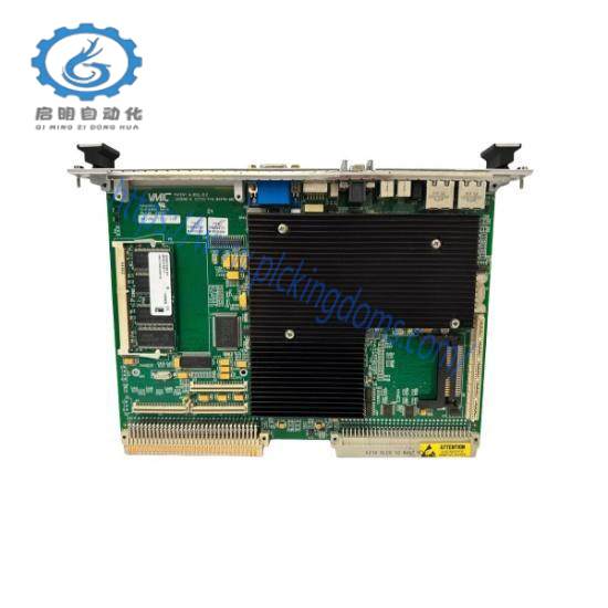
The VMIVME-7645 incorporates the latest Intel chipset technology, the 855GME. This chipset departs from previous generation devices by utilizing a new Advanced Hub Architecture (AHA). The AHA allows for increased system performance by separating many high-bandwidth I/O accesses (like IDE or USB devices) from PCI accesses, relieving bottlenecks on the PCI bus. Furthermore, the 855GME chipset brings new levels of integration to motherboard chipsets and provides additional features over other chipsets.
The Hance Rapids I/O Controller Hub (ICH) incorporates much of the hardware for the VMIVME-7645’s input/output ports, or drives the interfaces to which the controllers for the remainder of the I/O are connected. It includes support for two external PCI buses ( 32-bit 33MHz and 64-bit 66MHz), four USB ports, DMA controller, two 16550 serial ports, real-time clock, interrupt controller and Watchdog Timer.
Organization of the Manual
This manual is composed of the following chapters and appendices:
Chapter 1 – Installation and Setup describes unpacking, inspection, hardware jumper settings, connector definitions, installation, system setup and operation of the VMIVME-7645.
Chapter 2 – Standard Features describes the unit design in terms of the standard PC memory and I/O maps, along with the standard interrupt architecture.
Chapter 3 – Embedded PC/RTOS Features describes the unit features that are beyond standard functions.
Chapter 4 – Maintenance provides information relative to the care and maintenance of the unit.
Appendix A – Connector Pinouts illustrates and defines the connectors included in the unit’s I/O ports.
Appendix B – System Driver Software provides details for installing drivers under Windows XP.
Appendix C – AMI BIOS describes the menus and options associated with the AMI (system) BIOS.
Appendix D – Argon BIOS describes the menus and options associated with the LAN Boot BIOS.
Appendix E – Sample C Software provides example code to use with the VMIVME-7645.
Safety Summary
The following general safety precautions must be observed during all phases of the operation, service and repair of this product. Failure to comply with these precautions or with specific warnings elsewhere in this manual violates safety standards of design, manufacture and intended use of this product.
VMIC assumes no liability for the customer’s failure to comply with these requirements.
Ground the System
To minimize shock hazard, the chassis and system cabinet must be connected to an electrical ground. A three-conductor AC power cable should be used. The power cable must either be plugged into an approved three-contact electrical outlet or used with a three-contact to two-contact adapter with the grounding wire (green) firmly connected to an electrical ground (safety ground) at the power outlet.
Do Not Operate in an Explosive Atmosphere
Do not operate the system in the presence of flammable gases or fumes. Operation of any electrical system in such an environment constitutes a definite safety hazard.
Keep Away from Live Circuits
Operating personnel must not remove product covers. Component replacement and internal adjustments must be made by qualified maintenance personnel. Do not replace components with power cable connected. Under certain conditions, dangerous voltages may exist even with the power cable removed. To avoid injuries, always disconnect power and discharge circuits before touching them.
Notation and Terminology
This product bridges the traditionally divergent worlds of Intel-based PC’s and Motorola-based VMEbus controllers; therefore, some confusion over “conventional” notation and terminology may exist. Every effort has been made to make this manual consistent by adhering to conventions typical for the Motorola/VMEbus world; nevertheless, users in both camps should review the following notes:
Hexadecimal numbers are listed Motorola-style, prefixed with a dollar sign: $F79, for example. By contrast, this same number would be signified 0F79H according to the Intel convention, or 0xF79 by many programmers. Less common are forms such as F79h or the mathematician’s F7916
An 8-bit quantity is termed a “byte,” a 16-bit quantity is termed a “word,” and a 32-bit quantity is termed a “longword.” The Intel convention is similar, although their 32-bit quantity is more often called a “doubleword.”
Motorola programmers should note that Intel processors have an I/O bus that is completely independent from the memory bus. Every effort has been made in the manual to clarify this by referring to registers and logical entities in I/O space by prefixing I/O addresses as such. Thus, a register at “I/O $140” is not the same as a register at “$140,” since the latter is on the memory bus while the former is on the I/O bus.
• Intel programmers should note that addresses are listed in this manual using a linear, “flat-memory” model rather than the old segment:offset model associated with Intel Real Mode programming. Thus, a ROM chip at a segment:offset address of C000:0 will be listed in this manual as being at address $C0000. For reference, here are some quick conversion formulas:
Segment:Offset to Linear Address
Linear Address = (Segment × 16) + Offset
Linear Address to Segment:Offset
Segment = ((Linear Address ÷ 65536) − remainder) × 4096
Offset = remainder × 65536
Where remainder = the fractional part of (Linear Address ÷ 65536)
Note that there are many possible segment:offset addresses for a single location. The formula above will provide a unique segment:offset address by forcing the segment to an even 64 Kbyte boundary, for example, $C000, $E000, etc. When using this formula, make sure to round the offset calculation properly
Related product recommendations:
IC698CHS009A
SST-PFB-CLX
39PSR4ANDN
0190-15384
HIEE305082R0001
6ES7131-4RD02-0AB0
FS-IOCHAS-0001S
DSDX452
1794-ASB
DSRF199 3BSE019299R1
PCD231 B101 3BHE025541R0101
1769-IF4FXOF2F
1794-OE4
5501-372
505-7016
6ES7141-5AF00-0BA0
SNAT7780
IS200SPROH1ADD
DS200TCOBG1AEB
IS200AEADH3ADA
IC698CHS017 17
330103-00-08-05-02-CN
PFVK 135 3BSE007135R1
DS200TCQCG1AFC
EPRO R9268/203-000
IS200EMIOH1A
more……


Leave a comment
Your email address will not be published. Required fields are marked *